Home » Public Forums » GMCnet » Electrical gremlins, charging set up, and questions
| Re: Electrical gremlins, charging set up, and questions [message #310280 is a reply to message #310270] |
Sat, 12 November 2016 21:47   |
 Atom Ant

Messages: 170
Registered: October 2016
Location: Austin, TX
Karma: 0
|
Senior Member |
|
|
Atom Ant wrote on Sat, 12 November 2016 11:37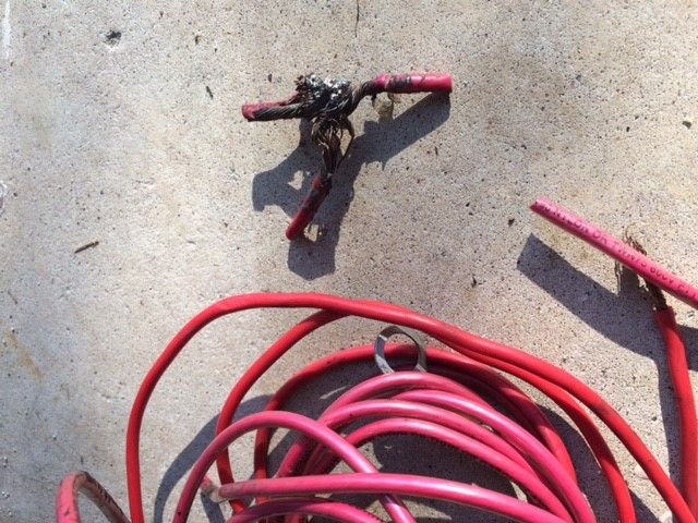
http://i66.photobucket.com/albums/h252/adammetzger/RIPballofwonder.jpg
I'd like to take a moment to remember the Ball of Wonder. 
Did some re-wiring this morning with my cup of coffee, and I think I've pulled about 30 ft. of wire total.
re-ran the alternator wire, with new waterproof terminals, and happy to say she cranked right up.
Now to re run the isolator, and then get busy with the fuel system.
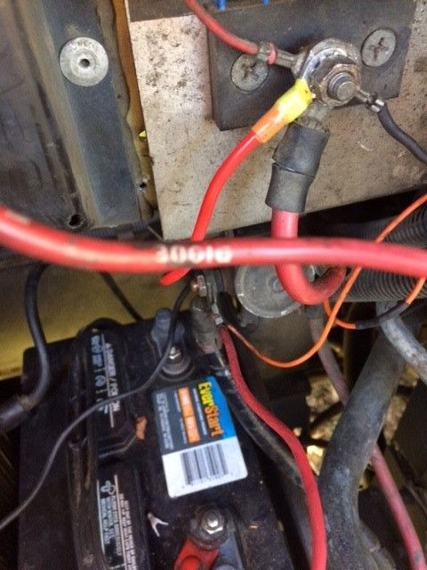
Can someone help me understand why there would be a wire from the positive side of the chassis battery to BOTH large terminals on the post solenoid? If one side is chassis, and the other side is house, why would there be wires from the positive battery post to each side? My positive has two terminal wires on POS.
1976 Palm Beach
Austin, TX
|
|
|
|
|
|
|
|
| Re: Electrical gremlins, charging set up, and questions [message #310290 is a reply to message #310284] |
Sun, 13 November 2016 09:21 |
 |
Matt Colie
Messages: 8547
Registered: March 2007
Location: S.E. Michigan
Karma: 7
|
Senior Member |
|
|
Atom Ant wrote on Sun, 13 November 2016 00:07I understand how it should be. I'm curious about why it is how it is now? Does that mean it's in a loop? Boosting off the same battery on boost mode?
Thanks for the patience with my questions!
Adam,
You and your coach have already earned a special place here. (That is not a bad thing.) That is because: A - You found us in time, B - You are paying attention.
We will have patience with your questions, and with the pictures you have shown I know I am expecting many more.
Why and how your PO did what he did we can only guess. All we can tell you for a fact is that it probably worked just fine forty-odd years ago. The original designs were good and there have been some technological improvements that many have included. But both here and on the boats that I have worked on over the years, there are often charges the value of which is beyond any understanding.
I do ask that you be patient with the answers you get here. If you do get a response that you do not understand (very possible) you come back with as best a question you can frame. Please realize that some here are very well educated and have decades of experience and may have to shift down a few gears to make an explanation that works for you. The may sound involved, but also remember that any answer is archived and someone else may benefit from it.
Isn't this an amazing group, family, cult, asylum???
Matt
Matt & Mary Colie - Chaumière -'73 Glacier 23 - Members GMCMI, GMCGL, GMCES
Electronically Controlled Quiet Engine Cooling Fan with OE Rear Drum Brakes with Applied Control Arms
SE Michigan - Near DTW - Twixt A2 and Detroit
|
|
|
|
|
|
| Re: Electrical gremlins, charging set up, and questions [message #310362 is a reply to message #309952] |
Mon, 14 November 2016 23:16 |
Atom Ant
Messages: 170
Registered: October 2016
Location: Austin, TX
Karma: 0
|
Senior Member |
|
|
Can I get a visual confirmation from someone?
My coach has a red wire coming out of the loom near the isolator that is factoey marked DIODE.
Is this the wire that runs to the alternator from the isolator?
My PO had another wire run to the alt, and this one is not connected.
1976 Palm Beach
Austin, TX
|
|
|
|
| Re: Electrical gremlins, charging set up, and questions [message #310384 is a reply to message #310362] |
Tue, 15 November 2016 11:46 |
roy1
Messages: 2126
Registered: July 2004
Location: Minden nevada
Karma: 6
|
Senior Member |
|
|
If there are 2 wires coming from the large terminal on the alternator to the center terminal of the diode I would leave them. The original factory wire is a little small in size here especially for those that switched to the 100 amp alternator. The extra wire I added to mine was #6.it did help in the short term when the batteries were low on charge.
Roy Keen
Minden,NV
76 X Glenbrook
|
|
|
|
| Re: Electrical gremlins, charging set up, and questions [message #310403 is a reply to message #309952] |
Tue, 15 November 2016 19:12 |
JohnL455
Messages: 4447
Registered: October 2006
Location: Woodstock, IL
Karma: 12
|
Senior Member |
|
|
The "2 wires" thing is something to be carefull with. You can disconnect both ends of what you think is the main alternator wire and beep it for continuity using an extension wire on one of the meter leads. You need to identify the "sense" wire. I don't have diagram up but I think other end goes to one of the sockets on the 2 prong connector.back of alternator This wire must go to the engine battery side of the isolator to read the .7V drop of the isolator so the slternator can compensate correctly. Your best ref would be a same year coach with unmolested wiring to go off of if anyone is near you.
John Lebetski
Woodstock, IL
77 Eleganza II
|
|
|
|
| Re: Electrical gremlins, charging set up, and questions [message #310407 is a reply to message #309952] |
Tue, 15 November 2016 21:19 |
Atom Ant
Messages: 170
Registered: October 2016
Location: Austin, TX
Karma: 0
|
Senior Member |
|
|
My isolator is completely dis connected. I'm trying to wire back to spec. PO had a mess of wires,
One of which ran from alt. To battery junction. There is a red wire marked DIODE coming out of the loom near the isolator. If I can use this wire instead of using a new one that I will have to also add another wire to the blower relay, I would prefer to use it.
Anyone with a 76 palm beach that wouldn't mind taking one more peek under their hood, i would appreciate it much.
1976 Palm Beach
Austin, TX
|
|
|
|
| Re: Electrical gremlins, charging set up, and questions [message #310417 is a reply to message #310403] |
Wed, 16 November 2016 02:59 |
Ken Burton
Messages: 10030
Registered: January 2004
Location: Hebron, Indiana
Karma: 10
|
Senior Member |
|
|
I believe the red wire in the loom that you are seeing goes to the fuse panel INSIDE the coach. If this is the wire that you are describing, then the end that you are looking at goes to a large terminal on the blower motor relay. From that same blower motor relay terminal there another 6" wire that goes to the isolator. That wire to the isolator is a 16 ga. fusible link.
I hope I am describing the wire you are asking about.
Ken Burton - N9KB
76 Palm Beach
Hebron, Indiana
|
|
|
|
|
|
|
|
| Re: Electrical gremlins, charging set up, and questions [message #310437 is a reply to message #310417] |
Wed, 16 November 2016 11:57 |
Atom Ant
Messages: 170
Registered: October 2016
Location: Austin, TX
Karma: 0
|
Senior Member |
|
|
Ken Burton wrote on Wed, 16 November 2016 02:59I believe the red wire in the loom that you are seeing goes to the fuse panel INSIDE the coach. If this is the wire that you are describing, then the end that you are looking at goes to a large terminal on the blower motor relay. From that same blower motor relay terminal there another 6" wire that goes to the isolator. That wire to the isolator is a 16 ga. fusible link.
I hope I am describing the wire you are asking about.
hi Ken-
I have two red wires coming out of the loom...one clearly marked DIODE.
http://i66.photobucket.com/albums/h252/adammetzger/1f9b4fed-99ee-4a94-82c4-e4a65b398bc8.jpg
The pic below shows the same DIODE wire coming off the frame to the right.
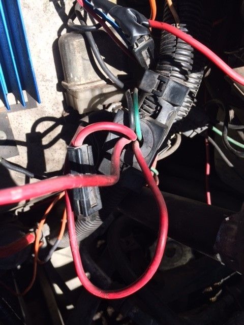
http://i66.photobucket.com/albums/h252/adammetzger/bc02e595-607a-4da1-b91f-d1cd83071d78.jpg
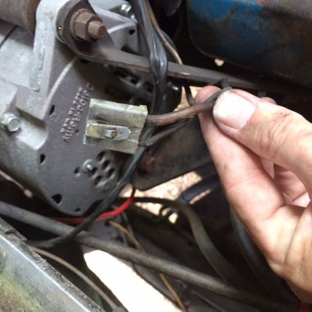
I think the wire you are referring to is the one I'm holding in the pic below?
also, am I mistaken that the red wire I'm holding goes to the horn relay, not the blower relay? (I thought the blower relay is the one above it)
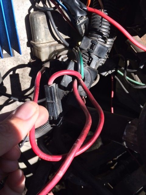
http://i66.photobucket.com/albums/h252/adammetzger/07725f97-0594-4d9c-ba6a-a9956ffbd9c2.jpg
How is your alternator wire run? Through the loom?
also, please notice my beautiful waterproof heat shrink and terminal work.

1976 Palm Beach
Austin, TX
[Updated on: Wed, 16 November 2016 12:07] Report message to a moderator |
|
|
|
|
|
| Re: Electrical gremlins, charging set up, and questions [message #310452 is a reply to message #310437] |
Thu, 17 November 2016 01:03 |
Ken Burton
Messages: 10030
Registered: January 2004
Location: Hebron, Indiana
Karma: 10
|
Senior Member |
|
|
Atom Ant wrote on Wed, 16 November 2016 11:57Ken Burton wrote on Wed, 16 November 2016 02:59I believe the red wire in the loom that you are seeing goes to the fuse panel INSIDE the coach. If this is the wire that you are describing, then the end that you are looking at goes to a large terminal on the blower motor relay. From that same blower motor relay terminal there another 6" wire that goes to the isolator. That wire to the isolator is a 16 ga. fusible link.
I hope I am describing the wire you are asking about.
hi Ken-
I have two red wires coming out of the loom...one clearly marked DIODE.
http://i66.photobucket.com/albums/h252/adammetzger/1f9b4fed-99ee-4a94-82c4-e4a65b398bc8.jpg
The pic below shows the same DIODE wire coming off the frame to the right.
http://i66.photobucket.com/albums/h252/adammetzger/bc02e595-607a-4da1-b91f-d1cd83071d78.jpg
I think the wire you are referring to is the one I'm holding in the pic below?
also, am I mistaken that the red wire I'm holding goes to the horn relay, not the blower relay? (I thought the blower relay is the one above it)
http://i66.photobucket.com/albums/h252/adammetzger/07725f97-0594-4d9c-ba6a-a9956ffbd9c2.jpg
How is your alternator wire run? Through the loom?
also, please notice my beautiful waterproof heat shrink and terminal work.
I believe that the red wire that you are holding is the one that feeds the fuse box inside the coach. That wire in the picture is currently connected to the correct place on the front of the Blower relay. If I said horn relay in a previous posting then I said it wrong. It should be the blower relay.
On the picture with the large single terminal with the big 1/2" nut on it, the little black wire going off to the lower right is the fusible link.
I can not give you the correct OEM alternator wire routing from the center terminal of the Isolator by looking at my coach. This is because my coach had an engine fire 7 years ago. I replaced all of the wiring on the top of the engine at that time. So mine is not stock (OEM).
The GMC wiring diagram says the alternator wire is a red 10 gauge one. I believe the one you are holding is a red 12 gauge one.
Someone else here will have to comment on the wire routing.
Ken Burton - N9KB
76 Palm Beach
Hebron, Indiana
|
|
|
|
| Re: Electrical gremlins, charging set up, and questions [message #310474 is a reply to message #309952] |
Thu, 17 November 2016 12:07 |
Atom Ant
Messages: 170
Registered: October 2016
Location: Austin, TX
Karma: 0
|
Senior Member |
|
|
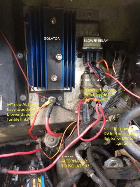
http://i66.photobucket.com/albums/h252/adammetzger/front%202%20notes.jpg
here is a overview pic with notes. according to my schematics, the relay with purple, black, dk blue, orange, and red dbl white wires is the BLOWER relay.
Thoughts?
1976 Palm Beach
Austin, TX
|
|
|
|
| Re: [GMCnet] Electrical gremlins, charging set up, and questions [message #310478 is a reply to message #310474] |
Thu, 17 November 2016 12:59 |
emerystora
Messages: 4442
Registered: January 2004
Karma: 13
|
Senior Member |
|
|
I have posted this several times over the years:
1973 through 1976 models had two relays in that area. The one above the horn is the blower relay for the heater/ air-conditioning blower.
Late 1977 and 1978 models had a third relay at the top which was a delay relay.
The delay relay is the smaller relay at the very top of the panel. It has two leads - on mine they are brown and yellow and one has a male and the other a female terminal at the end of the leads. The leads are approx. 6 to 8 inches long. The female one connects to the male terminal on the lead to the blower motor. The male one leads to the short lead (purple on mine) that goes to the blower relay (terminal 1). If the delay relay burns out you can plug the male motor lead directly into the short female lead going to terminal 1 on the blower relay.
The blower relay (below the delay relay but above the horn relay) has 5 terminals. When the blower relay is mounted with the 5 terminals down, there are two on the left, one in the middle and two on the right.
On the back left side it is #3 which has a red/white wire that leads to a fusible link and that goes into the harness and connects to the red wire from the alternator to the center stud of the battery isolater.
On the front left is terminal #2. Mine has a dark blue wire that leads to the resistor package in the right side of the heater box.
In the center is terminal #1. Mine has a short purple wire with a female connector. The male lead from the delay relay plugs into this (on mine right now I have the blower motor plugged into this as my delay relay is bad and disconnected).
On the right rear is terminal #5. This has a short black lead that goes to a ground screw.
On the right front is terminal #4. This has an orange wire that leads to the heater controls on the dash.
Terminals 4 & 5 control the coil in the blower relay.
Terminals 1 & 2 are normally closed and operate the blower when in low or medium speeds.
Terminal 1 & 3 are normally open but when the dash switch is put in "high" or "max" it actuates the coil and the relay connects these terminals which give power to the blower directly from the alternator in order to get higher voltage and higher blower speed. At the same time it disconnects terminal 2 from the circuit.
Emery Stora
77 Kingsley
Frederick, CO
> On Nov 17, 2016, at 11:07 AM, Adam Metzger wrote:
>
>
> http://i66.photobucket.com/albums/h252/adammetzger/front%202%20notes.jpg
>
> here is a overview pic with notes. according to my schematics, the relay with purple, black, dk blue, orange, and red dbl white wires is the BLOWER
> relay.
>
> Thoughts?
>
> --
> 1976 Palm Beach
> Austin, TX
>
> _______________________________________________
> GMCnet mailing list
> Unsubscribe or Change List Options:
> http://list.gmcnet.org/mailman/listinfo/gmclist_list.gmcnet.org
_______________________________________________
GMCnet mailing list
Unsubscribe or Change List Options:
http://list.gmcnet.org/mailman/listinfo/gmclist_list.gmcnet.org
|
|
|
|
| Re: Electrical gremlins, charging set up, and questions [message #310481 is a reply to message #309952] |
Thu, 17 November 2016 14:21 |
Atom Ant
Messages: 170
Registered: October 2016
Location: Austin, TX
Karma: 0
|
Senior Member |
|
|
I was hoping that the red wire marked DIODE would be the one to the alt, so I could just attach it to the ALT, and the isolator, then not have to deal with splitting my new wire, and I'm more comfortable using the wiring that was designed for it.
I guess I'm going to have to bust open the loom to dig deeper. I REALLY don't want to do that. literally a tube of worms.
1976 Palm Beach
Austin, TX
[Updated on: Thu, 17 November 2016 14:36] Report message to a moderator |
|
|
|
| Re: Electrical gremlins, charging set up, and questions [message #310486 is a reply to message #310481] |
Thu, 17 November 2016 15:23 |
Ken Burton
Messages: 10030
Registered: January 2004
Location: Hebron, Indiana
Karma: 10
|
Senior Member |
|
|
Now I am really confused after Emery's comments any your picture. Please ignore my comments regarding the blower vs. the horn relay. I have to go look at my coach to figure which one is which and the coach is not at home.
Sorry for the confusion on my part..
Ken Burton - N9KB
76 Palm Beach
Hebron, Indiana
|
|
|
|
| Re: Electrical gremlins, charging set up, and questions [message #310570 is a reply to message #309952] |
Fri, 18 November 2016 14:01 |
Atom Ant
Messages: 170
Registered: October 2016
Location: Austin, TX
Karma: 0
|
Senior Member |
|
|
My morning coffee cup update-
The red DIODE wire is indeed the wire that runs through the loom, across the top of the engine, and to the alternator. it is currently connected to the other wire running to the relay with the green fusible link correctly. unfortunately, the other end is utter shite. baked hard and covered in masses of electrical tape.
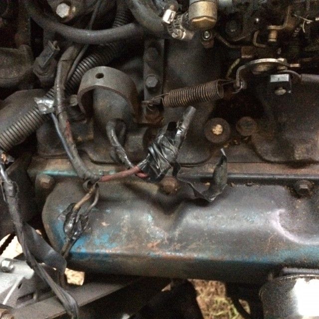
http://i66.photobucket.com/albums/h252/adammetzger/engine%20top%201.jpg
http://i66.photobucket.com/albums/h252/adammetzger/alt%20wire%201.jpg
old fly tying scissors are pretty good for cutting through this crap.
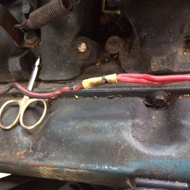
Why would someone double up the wire running from a single wire to a single terminal? Is this a thing?
http://i66.photobucket.com/albums/h252/adammetzger/engine%20top%202.jpg
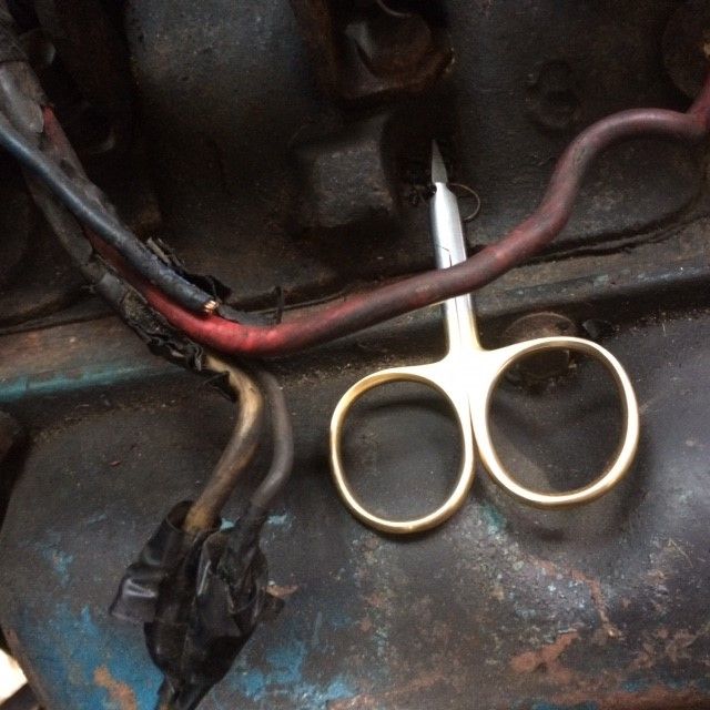
in unwrapping about 6 feet of old crusty electric tape, I found a suprise. A dk blue wire, cut at both ends, and wrapped up like a mummy. any ideas? runs to engine compartment, near battery?
BTW, that's the white wire that comes out of the ALT harness.
40 year old white male wire seeks alternator lifestyle for good times. 
I found a dorman replacement part for this, GMC from 73 to 90 something. the only concern is the wire gauge is smaller on the replacement. any issues? Should I pull it apart and use new wire correct gauge wire into the new part??
ideas?
Thanks fellas. I was TERRIFIED about the prospect of tearing into engine wiring. but alas, there are really only SO MANY wires, right?
thanks for the encouragement.
1976 Palm Beach
Austin, TX
[Updated on: Fri, 18 November 2016 14:39] Report message to a moderator |
|
|
|
Goto Forum:
Current Time: Thu Jul 04 22:48:41 CDT 2024
Total time taken to generate the page: 0.04938 seconds
|
 GMCforum


