Home » Public Forums » GMCnet » Electrical gremlins, charging set up, and questions
|
|
| Re: [GMCnet] Electrical gremlins, charging set up, and questions [message #310121 is a reply to message #310106] |
Tue, 08 November 2016 17:42   |
 k2gkk
k2gkk

Messages: 4452
Registered: November 2009
Karma: -8
|
Senior Member |
|
|
Since MOST of the wires for the Digipanel are color coded, I MAY use the small "bullet" type crimp connectors to split/join the wires before installing the panel. You could alternatively use Anderson PowerPole connectors. These non-polarized and insulated connectors are available in either 8 or 10 different colors and can even be joined together physically to make a pair of customized mating plugs that cannot be put together incorrectly! Now that I think of it, I believe this is the route I will take.
Lots of sources for these, but one I know of is www.powerwerx.com
You would want to use the 30 Amp housings and the 15 Amp "pins" for the small size of the Digipanel wires.
The special crimping tool is the most satisfactory means to make the connections, but is not absolutely necessary.
I plan to make the 2017 Shawnee Convention/Rally even if I can't get my coach running by then, and could easily bring my specialized tools to do these if there is a desire for me to do so.
~ ~ ~ ~ ~ ~ ~ ~ ~ ~ ~ ~ ~ ~ ~
~~ ~ D C "Mac" Macdonald ~ ~~
~ ~ Amateur Radio - K2GKK ~ ~
~ ~ Since 30 November '53 ~ ~
~ ~ USAF and FAA, Retired ~ ~
~ Member GMCMI and Classics ~
~ ~ ~ Oklahoma City, OK ~ ~ ~
~~ ~ ~ "The Money Pit" ~ ~ ~~
~ ~ ~ ~ TZE166V101966 ~ ~ ~ ~
~ ~ ~ '76 ex-Palm Beach ~ ~ ~
~~ k2gkk + hotmail dot com ~~
~ www.gmcmhphotos.com/okclb ~
~ ~ ~ ~ ~ ~ ~ ~ ~ ~ ~ ~ ~ ~ ~
______________
|[ ]~~~[][ ][]\
"--OO--[]---O-"
________________________________
From: Gmclist on behalf of Rob Mueller
Sent: Tuesday, November 8, 2016 14:46
To: gmclist@list.gmcnet.org
Subject: Re: [GMCnet] Electrical gremlins, charging set up, and questions
Jim,
I, for one, would be willing to pay more for the Digipanel IF the all the inputs were connected with connectors instead of being
hard wired to the unit.
Regards,
Rob M.
The Pedantic Mechanic
USAussie - Downunder
AUS '75 Avion - The Blue Streak TZE365V100428
USA '75 Avion - Double Trouble TZE365V100426
USA '77 Kingsley - TZE 267V100808
-----Original Message-----
From: Gmclist [mailto:gmclist-bounces@list.gmcnet.org] On Behalf Of Jim Kanomata
Sent: Wednesday, November 09, 2016 7:19 AM
To: gmclist@list.gmcnet.org
Subject: Re: [GMCnet] Electrical gremlins, charging set up, and questions
We are acquiring Digi Devices and should be in production in February.
We have a very qualified Engineer / Technician that will be heading that department.
This is a very reliable unit with audible warning and shows all the readings a one time, so one doesn't need to press buttons,
or glance around. This devise has saved many engines.
Jim Kanomata
Applied/GMC, Fremont, CA
jimk@appliedairfilters.com
http://www.appliedgmc.com
1-800-752-7502
_______________________________________________
GMCnet mailing list
Unsubscribe or Change List Options:
http://list.gmcnet.org/mailman/listinfo/gmclist_list.gmcnet.org
|
|
|
|
| Re: [GMCnet] Electrical gremlins, charging set up, and questions [message #310122 is a reply to message #310121] |
Tue, 08 November 2016 17:55 |
 |
USAussie
Messages: 15912
Registered: July 2007
Location: Sydney, Australia
Karma: 6
|
Senior Member |
|
|
Mac,
I thought of the same idea, however, you could run into a problem with the devices that read temperature. We might have to use one
of these depending on the sensor material:
Tiny URL: https://tinyurl.com/obx6fkf
Full URL.
https://www.google.com.au/search?sa=X&rlz=1C1PRFC_enAU683US686&espvd=2&biw=1137&bih=570&tbm=shop&q=thermocouple+connector& source=uni
v&tbo=u&ved=0ahUKEwje2M7CrJrQAhVJxrwKHV1nDngQ1TUIOSgH&dpr=0.9
We used a lot of copper constantan thermocouples to monitor temps on test equipment for Project Apollo. Having said that we were
interested in EXACT readings and on a GMC that isn't necessary.
Regards,
Rob M.
The Pedantic Mechanic
USAussie - Downunder
AUS '75 Avion - The Blue Streak TZE365V100428
USA '75 Avion - Double Trouble TZE365V100426
USA '77 Kingsley - TZE 267V100808
-----Original Message-----
From: D C _Mac_ Macdonald
Since MOST of the wires for the Digipanel are color coded, I MAY use the small "bullet" type crimp connectors to split/join the
wires before installing the panel. You could alternatively use Anderson PowerPole connectors. These non-polarized and insulated
connectors are available in either 8 or 10 different colors and can even be joined together physically to make a pair of customized
mating plugs that cannot be put together incorrectly! Now that I think of it, I believe this is the route I will take.
Lots of sources for these, but one I know of is www.powerwerx.com
You would want to use the 30 Amp housings and the 15 Amp "pins" for the small size of the Digipanel wires.
The special crimping tool is the most satisfactory means to make the connections, but is not absolutely necessary.
I plan to make the 2017 Shawnee Convention/Rally even if I can't get my coach running by then, and could easily bring my specialized
tools to do these if there is a desire for me to do so.
~~ ~ D C "Mac" Macdonald ~ ~~
_______________________________________________
GMCnet mailing list
Unsubscribe or Change List Options:
http://list.gmcnet.org/mailman/listinfo/gmclist_list.gmcnet.org
Regards,
Rob M. (USAussie)
The Pedantic Mechanic
Sydney, Australia
'75 Avion - AUS - The Blue Streak TZE365V100428
'75 Avion - USA - Double Trouble TZE365V100426
|
|
|
|
| Re: [GMCnet] Electrical gremlins, charging set up, and questions [message #310123 is a reply to message #310122] |
Tue, 08 November 2016 18:06 |
k2gkk
Messages: 4452
Registered: November 2009
Karma: -8
|
Senior Member |
|
|
I admit that I have not thoroughly investigated the theory of operation of all functions of the DigiPanel, but thought the unit simply converted voltages or resistances to operate the detection.
Mac in OKC
________________________________
From: Gmclist on behalf of Rob Mueller
Sent: Tuesday, November 8, 2016 17:55
To: gmclist@list.gmcnet.org
Subject: Re: [GMCnet] Electrical gremlins, charging set up, and questions
Mac,
I thought of the same idea, however, you could run into a problem with the devices that read temperature. We might have to use one
of these depending on the sensor material:
Tiny URL: https://tinyurl.com/obx6fkf
Full URL.
https://www.google.com.au/search?sa=X&rlz=1C1PRFC_enAU683US686&espvd=2&biw=1137&bih=570&tbm=shop&q=thermocouple+connector& source=uni
v&tbo=u&ved=0ahUKEwje2M7CrJrQAhVJxrwKHV1nDngQ1TUIOSgH&dpr=0.9
We used a lot of copper constantan thermocouples to monitor temps on test equipment for Project Apollo. Having said that we were
interested in EXACT readings and on a GMC that isn't necessary.
Regards,
Rob M.
The Pedantic Mechanic
USAussie - Downunder
AUS '75 Avion - The Blue Streak TZE365V100428
USA '75 Avion - Double Trouble TZE365V100426
USA '77 Kingsley - TZE 267V100808
-----Original Message-----
From: D C _Mac_ Macdonald
Since MOST of the wires for the Digipanel are color coded, I MAY use the small "bullet" type crimp connectors to split/join the
wires before installing the panel. You could alternatively use Anderson PowerPole connectors. These non-polarized and insulated
connectors are available in either 8 or 10 different colors and can even be joined together physically to make a pair of customized
mating plugs that cannot be put together incorrectly! Now that I think of it, I believe this is the route I will take.
Lots of sources for these, but one I know of is www.powerwerx.com
Anderson Powerpole, DC Power, Wire & Cable, Two-Way Radios | Powerwerx
www.powerwerx.com
Powerwerx offers Anderson Powerpole Connectors, Power Supplies, Battery Chargers, Wire & Cable, Mobile Timers much more. Shop online today!
You would want to use the 30 Amp housings and the 15 Amp "pins" for the small size of the Digipanel wires.
The special crimping tool is the most satisfactory means to make the connections, but is not absolutely necessary.
I plan to make the 2017 Shawnee Convention/Rally even if I can't get my coach running by then, and could easily bring my specialized
tools to do these if there is a desire for me to do so.
~~ ~ D C "Mac" Macdonald ~ ~~
_______________________________________________
GMCnet mailing list
Unsubscribe or Change List Options:
http://list.gmcnet.org/mailman/listinfo/gmclist_list.gmcnet.org
Gmclist Info Page - list.gmcnet.org
list.gmcnet.org
To see the collection of prior postings to the list, visit the Gmclist Archives. Using Gmclist: To post a message to all the list members, send email ...
_______________________________________________
GMCnet mailing list
Unsubscribe or Change List Options:
http://list.gmcnet.org/mailman/listinfo/gmclist_list.gmcnet.org
|
|
|
|
| Re: Electrical gremlins, charging set up, and questions [message #310146 is a reply to message #309952] |
Wed, 09 November 2016 08:12 |
jhbridges
Messages: 8412
Registered: May 2011
Location: Braselton ga
Karma: -74
|
Senior Member |
|
|
I'd ask before I spliced the temp sensor wires. The pressure sender wire can be spliced wothout worry, since it sees 90 Ohms to zero, wire resistance isn't gonna matter till you get into the hundreds of feet. The temp sensing thermistors may or may not be sensitive enough to worry over, ask first. They can be recalibrated if there's a problem with more wire.
--johnny
Foolish Carriage, 76 26' Eleganza(?) with beaucoup mods and add - ons.
Braselton, Ga.
I forgive them all, save those who hurt the dogs. They must answer to me in hell
|
|
|
|
| Re: Electrical gremlins, charging set up, and questions [message #310157 is a reply to message #309952] |
Wed, 09 November 2016 12:54 |
Atom Ant
Messages: 170
Registered: October 2016
Location: Austin, TX
Karma: 0
|
Senior Member |
|
|
Thanks Johnny! I'm in the process of gathering supplies for the re wire.
I do have a question though....
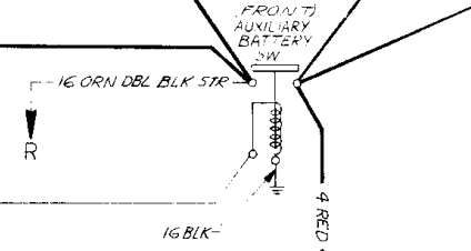
I'm the schematics, there are wires that come off in some instances that show an arrow and a single non boxed letter. Not the boxed double letters designated in the key.
For example, there is a 12 ga red wire coming off the 10 ga red wire going to the isolator from the generator.
This wire goes to X.
There is also a 16 ga org dbl blk wire coming off the front switch, going to R.
What am I missing?
1976 Palm Beach
Austin, TX
|
|
|
|
| Re: Electrical gremlins, charging set up, and questions [message #310158 is a reply to message #310157] |
Wed, 09 November 2016 13:13 |
A Hamilto
Messages: 4508
Registered: April 2011
Karma: 39
|
Senior Member |
|
|
Atom Ant wrote on Wed, 09 November 2016 12:54Thanks Johnny! I'm in the process of gathering supplies for the re wire.
I do have a question though....
I'm the schematics, there are wires that come off in some instances that show an arrow and a single non boxed letter. Not the boxed double letters designated in the key.
For example, there is a 12 ga red wire coming off the 10 ga red wire going to the isolator from the generator.
This wire goes to X.
There is also a 16 ga org dbl blk wire coming off the front switch, going to R.
What am I missing? On the schematic for mine, there is an arrow pointing down to an X and lower down the drawing there is an arrow pointing up to an X. I am sure that just means they didn't clutter up the drawing with a line all the way from one to the other.
If yours doesn't have another X or another R, your drawing must be incomplete.
And the other X is the power wire for the dash heat/AC blower high speed.
[Updated on: Wed, 09 November 2016 13:24] Report message to a moderator |
|
|
|
| Re: Electrical gremlins, charging set up, and questions [message #310162 is a reply to message #310158] |
Wed, 09 November 2016 16:06 |
Atom Ant
Messages: 170
Registered: October 2016
Location: Austin, TX
Karma: 0
|
Senior Member |
|
|
A Hamilto wrote on Wed, 09 November 2016 13:13Atom Ant wrote on Wed, 09 November 2016 12:54Thanks Johnny! I'm in the process of gathering supplies for the re wire.
I do have a question though....
I'm the schematics, there are wires that come off in some instances that show an arrow and a single non boxed letter. Not the boxed double letters designated in the key.
For example, there is a 12 ga red wire coming off the 10 ga red wire going to the isolator from the generator.
This wire goes to X.
There is also a 16 ga org dbl blk wire coming off the front switch, going to R.
What am I missing? On the schematic for mine, there is an arrow pointing down to an X and lower down the drawing there is an arrow pointing up to an X. I am sure that just means they didn't clutter up the drawing with a line all the way from one to the other.
If yours doesn't have another X or another R, your drawing must be incomplete.
And the other X is the power wire for the dash heat/AC blower high speed.
Of course. Thank you!
1976 Palm Beach
Austin, TX
|
|
|
|
| Re: Electrical gremlins, charging set up, and questions [message #310203 is a reply to message #309952] |
Thu, 10 November 2016 14:20 |
David del Rio
Messages: 49
Registered: April 2016
Location: Raymond CA
Karma: 0
|
Member |
|
|
Chris commented... "Batteries should never be hooked up inside the passenger compartment as they off gas hydrogen while charging. One word? Hindenburg."
While I don't disagree, I wanted to note that in my '75 Avion the house battery stock location is in a metal box with a foam sealed lid, that is vented by an inch and a half diameter tube that exits less than a foot away behind the license plate.
Question: Is this stock arrangement dangerous?
Thank you!
Dave
David del Rio - 75 Avion - Raymond, CA
|
|
|
|
|
|
| Re: Electrical gremlins, charging set up, and questions [message #310206 is a reply to message #310203] |
Thu, 10 November 2016 14:30 |
 |
Matt Colie
Messages: 8547
Registered: March 2007
Location: S.E. Michigan
Karma: 7
|
Senior Member |
|
|
David del Rio wrote on Thu, 10 November 2016 15:20Chris commented... "Batteries should never be hooked up inside the passenger compartment as they off gas hydrogen while charging. One word? Hindenburg."
While I don't disagree, I wanted to note that in my '75 Avion the house battery stock location is in a metal box with a foam sealed lid, that is vented by an inch and a half diameter tube that exits less than a foot away behind the license plate.
Question: Is this stock arrangement dangerous?
Thank you!
Dave
Dave,
No
Discussion.
While batteries don't actually vent that much hydrogen, but they do vent a near perfect mixture of hydrogen and oxygen. So the real idea is to vent it out to where it is less likely to find a source of ignition. With no place for it to accumulate and no handy ignition source, what you have is about as safe as you can be.
Matt
Matt & Mary Colie - Chaumière -'73 Glacier 23 - Members GMCMI, GMCGL, GMCES
Electronically Controlled Quiet Engine Cooling Fan with OE Rear Drum Brakes with Applied Control Arms
SE Michigan - Near DTW - Twixt A2 and Detroit
|
|
|
|
| Re: Electrical gremlins, charging set up, and questions [message #310216 is a reply to message #309952] |
Thu, 10 November 2016 18:04 |
Atom Ant
Messages: 170
Registered: October 2016
Location: Austin, TX
Karma: 0
|
Senior Member |
|
|
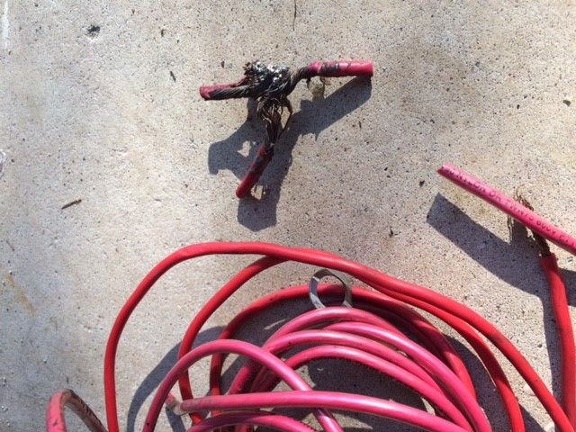
http://i66.photobucket.com/albums/h252/adammetzger/boost%20switch.png
If I had a switch in my hand, not connected to anything, and needed to attach the wires to this, how would I determine which wires go where?
how does one know which of the 4 posts leads to where? I don't have the part in front of me, so if there are indentifying marks, forgive me.
1976 Palm Beach
Austin, TX
|
|
|
|
| Re: Electrical gremlins, charging set up, and questions [message #310227 is a reply to message #310216] |
Thu, 10 November 2016 22:18 |
Ken Burton
Messages: 10030
Registered: January 2004
Location: Hebron, Indiana
Karma: 10
|
Senior Member |
|
|
You need to explain what you plan to turn off and on with that switch before we answer.
If you connect to one side of the solenoid you will get house battery power.
If you connect to the other side of the solenoid you with get engine battery power.
BOTH OF THESE CONNECTIONS ARE NOT FUSED.
Ken Burton - N9KB
76 Palm Beach
Hebron, Indiana
|
|
|
|
|
|
| Re: Electrical gremlins, charging set up, and questions [message #310231 is a reply to message #310228] |
Fri, 11 November 2016 01:58 |
Ken Burton
Messages: 10030
Registered: January 2004
Location: Hebron, Indiana
Karma: 10
|
Senior Member |
|
|
OK, I think I understand the question now.
The item you are looking at we call a boost solenoid or boost relay.
First is the small terminals. One goes to the thin wire going to the boost switch on the dash and one goes to ground. The polarity is not important, so just wire one to the boost switch on the dash and the other one to engine battery ground. The aluminum plate where the relay/solenoid is mounted is connected to engine battery ground and that is where GM wired their's.
On the big terminals, which side you use there is also unimportant as long as you get the correct together wires on each side. (The three red on the right side of the diagram on one side, and the other two on the left side of the diagram on the other terminal.
One side is engine battery circuits and the other side is house battery circuits. They can not be mixed from side to side. I forget at the moment which side Gm used for which and my coach is not here for me to look at. It will not hurt which side you use for them as long as wires for the two sides are not mixed.
Clear as mud. right?
Ken Burton - N9KB
76 Palm Beach
Hebron, Indiana
|
|
|
|
| Re: Electrical gremlins, charging set up, and questions [message #310238 is a reply to message #310231] |
Fri, 11 November 2016 10:20 |
A Hamilto
Messages: 4508
Registered: April 2011
Karma: 39
|
Senior Member |
|
|
Ken Burton wrote on Fri, 11 November 2016 01:58OK, I think I understand the question now.
The item you are looking at we call a boost solenoid or boost relay.
First is the small terminals. One goes to the thin wire going to the boost switch on the dash and one goes to ground. The polarity is not important, so just wire one to the boost switch on the dash and the other one to engine battery ground. The aluminum plate where the relay/solenoid is mounted is connected to engine battery ground and that is where GM wired their's.
On the big terminals, which side you use there is also unimportant as long as you get the correct together wires on each side. (The three red on the right side of the diagram on one side, and the other two on the left side of the diagram on the other terminal.
One side is engine battery circuits and the other side is house battery circuits. They can not be mixed from side to side. I forget at the moment which side Gm used for which and my coach is not here for me to look at. It will not hurt which side you use for them as long as wires for the two sides are not mixed.
Clear as mud. right? I will add a few details that might make it a little clearer.
One large post is the house battery, one large post is the chassis battery, one small post is the power for the plunger (goes to the boost switch) and the other small post is the ground for the plunger.
Your schematic is different than mine, so I can only describe mine (which has one more wire on the house battery terminal).
The left side is the chassis battery side. One #4 red wire goes to the "battery pickup junction box" (where the power comes from the alternator through the isolator, through a #10 red wire to the battery pickup junction box, and charges the battery). One #4 red wire goes to the starter. One #4 red wire goes to the chassis battery.
The right side is the house battery side. One #10 red wire goes through a 50A fuse to the house battery bus bar. One #10 red wire goes to the isolator (to charge the house battery) and the #4 red wire goes to the house battery.
|
|
|
|
|
|
| Re: Electrical gremlins, charging set up, and questions [message #310256 is a reply to message #310238] |
Fri, 11 November 2016 17:12 |
Atom Ant
Messages: 170
Registered: October 2016
Location: Austin, TX
Karma: 0
|
Senior Member |
|
|
A Hamilto wrote on Fri, 11 November 2016 10:20Ken Burton wrote on Fri, 11 November 2016 01:58OK, I think I understand the question now.
The item you are looking at we call a boost solenoid or boost relay.
First is the small terminals. One goes to the thin wire going to the boost switch on the dash and one goes to ground. The polarity is not important, so just wire one to the boost switch on the dash and the other one to engine battery ground. The aluminum plate where the relay/solenoid is mounted is connected to engine battery ground and that is where GM wired their's.
On the big terminals, which side you use there is also unimportant as long as you get the correct together wires on each side. (The three red on the right side of the diagram on one side, and the other two on the left side of the diagram on the other terminal.
One side is engine battery circuits and the other side is house battery circuits. They can not be mixed from side to side. I forget at the moment which side Gm used for which and my coach is not here for me to look at. It will not hurt which side you use for them as long as wires for the two sides are not mixed.
Clear as mud. right? I will add a few details that might make it a little clearer.
One large post is the house battery, one large post is the chassis battery, one small post is the power for the plunger (goes to the boost switch) and the other small post is the ground for the plunger.
Your schematic is different than mine, so I can only describe mine (which has one more wire on the house battery terminal).
The left side is the chassis battery side. One #4 red wire goes to the "battery pickup junction box" (where the power comes from the alternator through the isolator, through a #10 red wire to the battery pickup junction box, and charges the battery). One #4 red wire goes to the starter. One #4 red wire goes to the chassis battery.
The right side is the house battery side. One #10 red wire goes through a 50A fuse to the house battery bus bar. One #10 red wire goes to the isolator (to charge the house battery) and the #4 red wire goes to the house battery.
Thank you both for explaining. I have the wiring diagrams, and can follow them. I actually also wrote down directions, almost like driving directions, to hel pme make sure I got it all, and hopefully help understand the flow better in the future, when I'm broken down on the side of the road with a wife, 4 kids, a dog, and a Dad that doesn't think things like that are funny until were about 100 miles away from them. 
My question was much more general in nature. I guess what I was asking was about polarity, and knowing what wires to put where. You cleared it up by telling me that it didn't matter, as long as they were all on the same side. (ie, chassis together, house together)
1976 Palm Beach
Austin, TX
|
|
|
|
|
|
|
|
Goto Forum:
Current Time: Fri Oct 04 01:57:39 CDT 2024
Total time taken to generate the page: 0.00976 seconds
|
 GMCforum


