| Need Onan help [message #255722] |
Thu, 17 July 2014 17:27  |
 larry.whisler

Messages: 356
Registered: August 2005
Karma: 8
|
Senior Member |
|
|
I recently had some issues with trying to get the Onan to start
and continue running and decided to replace all of the flag
quick disconnects on the plug wires.
so, pulled the plug wires and connectors from the board and did
the replacement. Now I am reconnecting the wire set and not sure
if I have each of the wires going to the correct posts on the board.
I tried to find a diagram but had no luck. closest diagram I could
find was on bdub's site on the dinosaur board.
I am wanting to check pins 4 through 6 for correctness.
Can someone point me to a diagram?
thanks
larry
|
|
|
|
|
|
|
|
|
|
| Re: [GMCnet] Need Onan help [message #255748 is a reply to message #255745] |
Thu, 17 July 2014 20:04  |
A Hamilto
Messages: 4508
Registered: April 2011
Karma: 39
|
Senior Member |
|
|
larry.whisler wrote on Thu, 17 July 2014 19:43Wally & Gene,
thanks for the links to the diagrams.
As Gene Simmons stated in his writeup, the wires are marked with the board terminal numbers, but I find that his diagram and the 'yuno_board' diagram are not the same.
Wires 1 & 2 are switched on Gene Simmons diagram
and wire 5 is going to terminal 6.
and wire 4 is going to T1 which I think is terminal 1A on the juno diagram.
So, I am confused as to wire 5 connecting to terminal 6 and the wires 1 & 2 being switched on the board.
Any idea(s) as to what is correct?
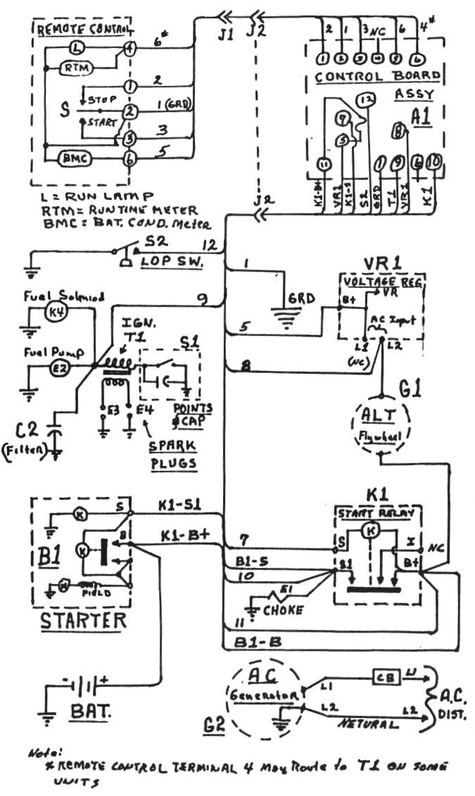
larry Note: Pins 1 to 6 have two pins each, one across the top to connect to the remote and another down lower, mixed in with the rest of the stuff.
Pin 1 is ground for the board. it is also connected to the remote, providing a ground to the remote switch.
Pin 2 is the input to the board for the remote stop function. Grounding this pin cause the board to shut off the generator.
Pin 3 is the input to the board for the remote start function. Grounding this pin cause the board to start the generator.
Pin 4 doesn't seem to be used in our application. Looks like another input into the same circuits that the oil pressure switch connect to.
Pin 5 is FUSED 12 volts from the battery.
Pin 6 has 12volts (fused) only when the generator is running.
Pin 7 is the ground side of the coil of the start solenoid. Grounding this point should cause the starter to engage.
Pin 8 is an A/C "generator running" input to the board from the flywheel alternator. (The other side of this AC signal is pin 5.) It disengages the starter and "latches" the voltage provided to pin 9.
Pin 9 is the output of the board to BOTH the ignition and the fuel pump. If there is voltage here, the pump should be running and the points/coil should have power.
Pin 10 has 12volts from the starter solenoid when the starter is engaged. It provides power to pin 9 when starting.
Pin 11 is UN-FUSED 12 volts from the battery.
Pin 12 is the input of the board from the oil pressure switch. The switch applies a ground when there isn't oil pressure. Just disconnecting this pin disables the function.
NOW for the methods of jumping (bypassing):
The main differences in jumping is where the power comes from, all of them connect to pin 9 (electrically the same point as the + side of the coil, the fuel pump and the fuel shut-off solenoid):
Method 1.) Some jump from pin 11 but it is better to use fused power on pin 5. It pin 11 works but pin 5 does not, look at the fuse.
Method 2.) The most popular spot is pin 5. You still use the button on the board to get the starter to turn. But you need to un-jumper the pins to turn off the generator.
Method 3.) Relatively unknown method is pin 6. This disables the generator running and low oil pressure functions but maintains BOTH the start AND STOP functions of the board. As the lower pin 6 is right next to pin 9, a short one inch jumper can be left in place with the cover on and genset pushed back in the "Onan-hole." Be aware that if you try to start the generator but it doesn't start, there will still be power to the pump and ignition until you press "stop." While all methods keep the power on pin 9, it is just easier to forget without a wire hanging off the generator.
|
|
|
|
| Re: [GMCnet] Need Onan help [message #255753 is a reply to message #255745] |
Thu, 17 July 2014 20:45 |
A Hamilto
Messages: 4508
Registered: April 2011
Karma: 39
|
Senior Member |
|
|
larry.whisler wrote on Thu, 17 July 2014 19:43...Wires 1 & 2 are switched on Gene Simmons diagram
and wire 5 is going to terminal 6.
and wire 4 is going to T1 which I think is terminal 1A on the juno diagram.
So, I am confused as to wire 5 connecting to terminal 6 and the
wires 1 & 2 being switched on the board.
Any idea(s) as to what is correct?... What the diagram shows is that
pin 1 on the Onan board goes to connector 2 on the remote start/stop switch,
pin 2 on the Onan board goes to connector 1 on the remote start/stop switch,
pin 3 on the Onan board goes to connector 3 on the remote start/stop switch,
pin 4 on the Onan board is not used,
pin 6 on the Onan board goes to connector 4 on the remote start/stop switch,
pin 5 on the Onan board goes to connector 6 on the remote start/stop switch.
|
|
|
|
 GMCforum
